
Future airborne software will follow an assurance process appropriate to the vehicle's eventual system-safety classification and certification basis.
VEHICLE PROGRAM
The Orbiter
A vehicle shaped by the mission.
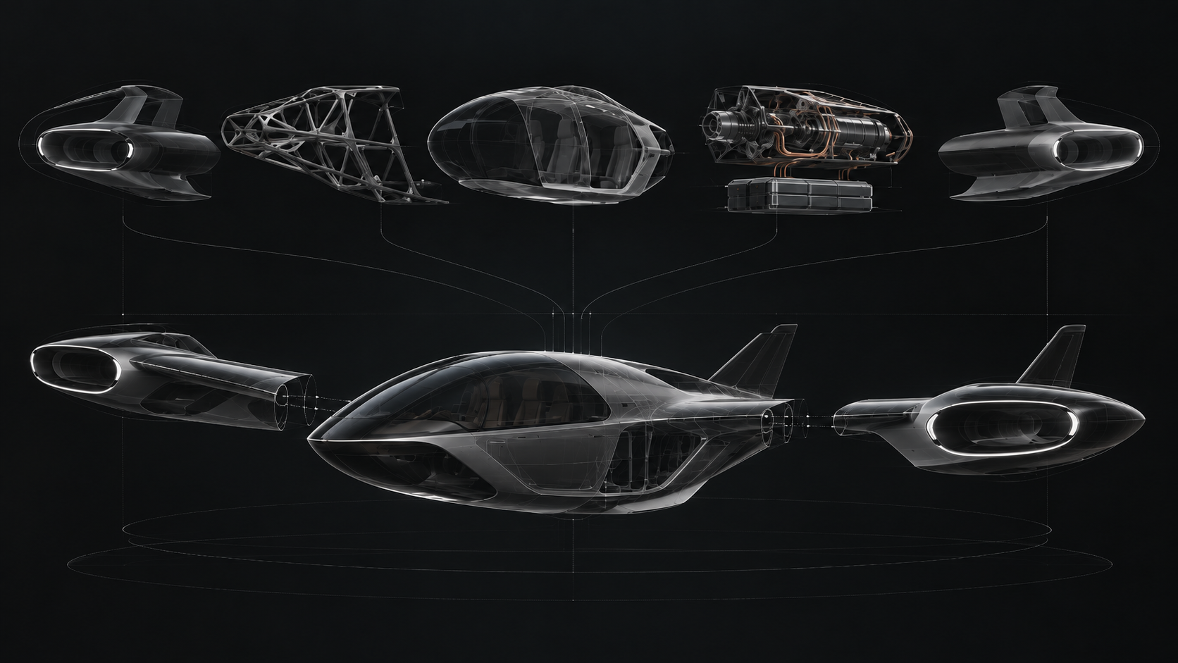
Ascerex is developing a compact VTOL aircraft around a demanding premise: meaningful payload, road-width packaging, and contained propulsion in one integrated system.
Explore the vehicleCurrent development focusComputational evaluation — fixed-span flight + enclosed vectored thrust
The vehicle brief
What the vehicle must do
Orbiter begins with a narrow set of non-negotiable design inputs. Those inputs force propulsion, airframe, energy, and control decisions to converge around the same vehicle.
Computational engineering and analytical screening are active. Configuration selection follows integrated feasibility gates.
These are program requirements for engineering evaluation, not demonstrated aircraft performance.
- 1,000+LB
- Payload requirementThe working requirement is sized around five nominal 200 lb occupants.
- 8FT
- Road-width envelopeThe vehicle must fit within an eight-foot stowed width.
- VTOL
- Operating requirementVertical takeoff and landing shape every downstream architecture trade.
- 0EXPOSED
- Propellers or rotorsThe current requirement keeps thrust-producing hardware contained.
Orbiter architecture
How Orbiter is developed
Orbiter is developed as one coupled system: vehicle envelope, wing and body lift, contained propulsion, energy, structure, thermal behavior, stability, and control must resolve the same mission. The program advances through traceable gates, and new evidence can return a configuration to an earlier stage.
- 01Established foundation
Define requirements
Establish mission, payload, geometry, containment, safety, and operating constraints.
- 02Analytical framework
Model mission demand
Translate each flight phase into force, lift, power, energy, thermal, and control demands under explicit assumptions.
- 03Current active stage
Screen architectures
Qualify evidence and compare propulsion and energy approaches using applicable models and traceable gates.
- 04Coupled evaluation
Integrate the vehicle
Couple geometry, propulsion, aerodynamics, structure, mass, energy, thermal behavior, controls, packaging, and landing systems.
- 05Progressive fidelity
Advance viable configurations
Move surviving configurations into higher-fidelity simulation, integration studies, subsystem testing, and controlled physical testing.
The sequence is iterative. A result can revise an assumption, requirement, model, or configuration before the program advances.
Propulsion research & development
From evidence to engineering decisions
Ascerex is building a computational workflow that turns propulsion research into vehicle-level decisions. The records below track the families under investigation, the studies carried out, and the constraints shaping the next step.
01 Evidence organized +Sources → structured records
Source claims are traced to their origin, classified by propulsion family, and checked for the inputs a model requires. Missing evidence stays visible.
02 Models applied +Physics → power, energy & mass
Applicable physics models connect flight demand to installed capability. Bounded studies vary assumptions to expose the constraints that dominate a case.
03 Decisions recorded +Finding → status & next step
Each record explains what the evidence supports, what limits the result, and why a study proceeds, pauses, or stops under its tested assumptions.
Research families & architecture studies
Select a record to explore the evidence and takeaway.Study outcomes apply to the configurations and assumptions evaluated. No propulsion architecture has been selected.
Coupled aircraft architecture
Airframe and vehicle integration
No subsystem can be selected independently of the complete vehicle. Packaging, loads, power, heat, control, and aerodynamic behavior must close around one configuration.
- Parametric geometry
- Wing and body aerodynamics
- Occupant and payload packaging
- Structural load paths
- Landing systems
Coupled vehicle model
Orbiter configuration
Mission fit, road-width storage, installed performance, mass closure, and operating limits are resolved as one system.
8 FT STOWED ENVELOPE- Propulsion placement
- Center of mass and distribution
- Energy storage and power
- Thermal management
- Controls and operating envelope
The fixed-span vehicle is the current baseline. A deployable wing remains a fallback if the integrated fixed-span system does not satisfy feasibility gates now being defined.
Engineering rules encoded in the workflow
- Requirements, assumptions, evidence, models, results, and decisions remain traceable.
- Configured studies can be reproduced from versioned inputs and declared model boundaries.
- Propulsion families route only to physics models that apply to their mechanisms.
- Missing information remains unknown, and hard constraints are evaluated before comparison.
Program discipline
Assurance begins with the requirements
Regulatory, safety, airspace, software-assurance, and operating-approval considerations enter the requirements and verification process from the beginning.
Explore the mission framework↗